
Industrial Load Cell Sourcing Guide: Engineering, Selection, and Deployment Framework
Sourcing and integrating force measurement hardware into industrial automation frameworks requires navigating a complex landscape of mechanical, environmental, and electrical parameters. Choosing an incorrect sensor architecture leads to calibration drift, measurement errors, or premature mechanical failure, all of which disrupt operations and increase ownership costs.
Procurement managers frequently focus on unit cost and nominal capacity, while instrumentation engineers prioritize long-term stability, excitation accuracy, and thermal hysteresis. This guide bridges that gap, providing an actionable engineering and sourcing framework for control engineers, procurement officers, and R&D designers. By focusing on structural mechanics, aggressive environment scaling, and electronic interfaces, this manual transforms abstract sensor theory into concrete implementation strategies for high-capacity process plants and precision automated machinery.
NOTE: Most industrial load cells rely on bonded metallic foil strain gauges as their primary sensing elements. Learn more about Wheatstone bridge topologies and signal conditioning in our Foil Strain Gauge Engineering Guide. For high-EMI environments requiring direct RS-485, CANbus, or IO-Link telemetry without summing junction boxes, explore our Digital Load Cell Architecture & Bus Integration Guide.
Key Takeaways
- Load Cell Operating Mechanism: A load cell is an engineered transducer that converts mechanical force into a precise electrical signal via strain gauges bonded to an elastic element arranged in a Wheatstone bridge.
- Mechanical Vector Selection: Matching the sensor geometry (S-Beam, Canister, Pancake, Shear Beam) to primary directional load paths (tension, compression, universal) is critical to prevent side-load distortion and material fatigue.
- Environmental & CIP Protection: Industrial washdown environments require laser-welded stainless steel hermetic seals (IP69K) and PTFE-jacketed cabling to resist thermal expansion stresses and chemical hydrolytic cleavage from sodium hydroxide and nitric acid.
- Signal Conditioning & Cable Runs: Long distance cable runs require 6-wire sense lead topologies or amplified 4–20 mA current loops to eliminate voltage attenuation and electromagnetic interference (EMI) near high-power VFD lines.
1. What is a Load Cell & How Does It Work?
A load cell is a precision transducer designed to convert applied mechanical force into a proportional electrical signal, enabling accurate force measurement, load tracking, and industrial weighing across manufacturing, structural monitoring, and process automation environments.
Engineered for integration with control systems requiring high linearity and low hysteresis, a load cell serves as the foundational component in industrial weighing systems, platform scales, hopper scales, crane scales, and OEM automated machinery.
Principles of Strain Gauge Operation
The sensing core of a strain gauge load cell consists of an elastic spring element—typically machined from high-strength alloy steel, stainless steel, or aluminum—and precision foil strain gauges bonded directly to its surface.

When mechanical force is applied, the elastic element undergoes microscopic deformation. Attached strain gauges experience corresponding physical stretch or compression, altering their internal electrical resistance.
The sensitivity of a strain gauge is defined by its Gauge Factor (GF):
GF = (ΔR / R₀) / ε
Where ΔR is the resistance change, R₀ is initial resistance, and ε is mechanical strain.
The Wheatstone Bridge Circuit
To detect micro-ohm resistance shifts, four strain gauges are arranged in a Wheatstone bridge circuit. This topology maximizes electrical sensitivity while canceling out thermal expansion errors caused by ambient temperature changes.
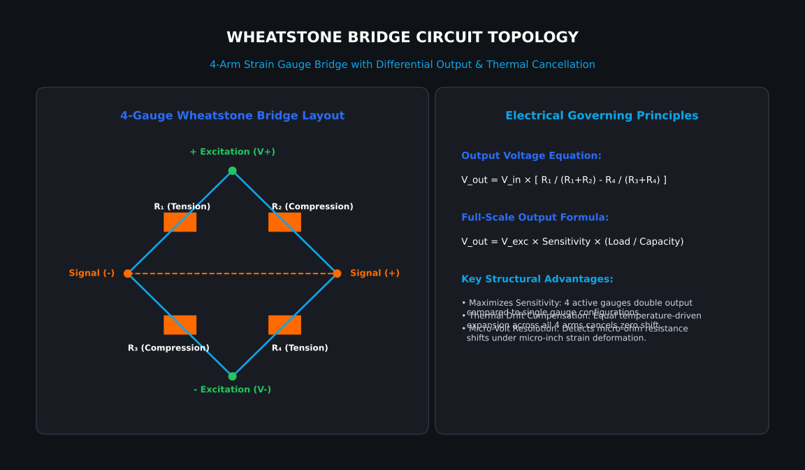
The output voltage (Vout) generated by the Wheatstone bridge is calculated as:
Vout = Vin × [ R₁ / (R₁ + R₂) – R₄ / (R₃ + R₄) ]
Electrical Signal Output & mV/V Sensitivity
Raw analog load cells produce a low-level ratiometric signal measured in millivolts per volt (mV/V). Maximum signal output is directly proportional to both applied load and excitation voltage provided by the weight controller:
Output Voltage = Excitation Voltage × Sensitivity Rating × (Applied Load / Full Scale Capacity)
Real-World Output Example:
- Sensor Capacity: 10,000 lbs
- Sensitivity Rating: 2.0 mV/V
- Excitation Voltage: 10 V DC
At full 10,000 lb capacity:
10 V DC × 2.0 mV/V = 20.0 mV
At a partial load of 2,500 lbs, the output drops to 5.0 mV. Because weight increments correspond to microvolt variations (1 µV = 0.000001 V), signal conditioning and noise protection are essential.
2. Mechanical Form Factors & Directional Vector Selection
Selecting a load cell requires understanding how mechanical forces move through an assembly. Transducers must measure primary force vectors while surviving multi-axis parasitic forces encountered during plant operations.
Structural Constraints: Tension, Compression, and Universal Loads
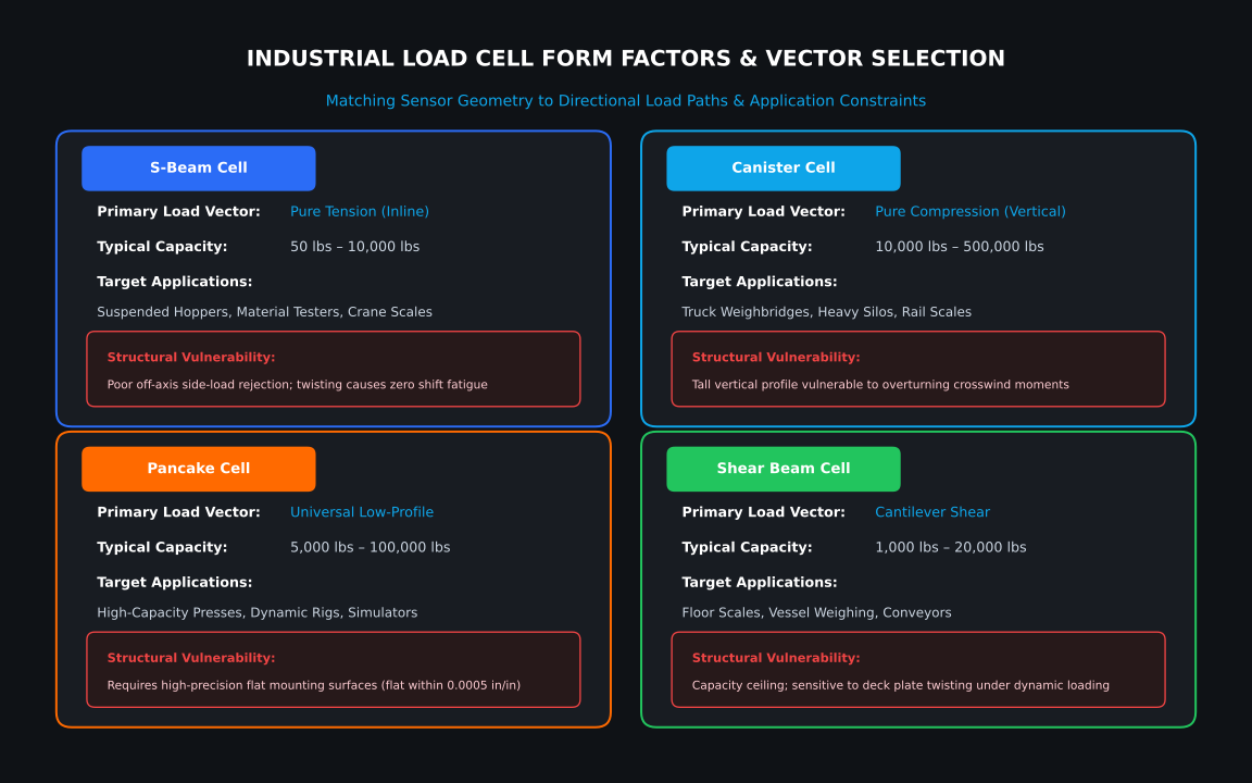
S-Beam Load Cells (Pure Tension)
S-Beam sensors operate via bending or shear strain mechanics when tensile loads pull on upper and lower integrated threads.
- Mechanical Suitability: Ideal for suspended vessels, mechanical scale conversions, hopper weighing, and inline material testing.
- Structural Vulnerability: Poor off-axis side-load rejection. Twisting or swaying introduces asymmetric strains across the central web, distorting Wheatstone bridge balance and causing zero-shift fatigue failures.
Canister Load Cells (Pure Compression)
Canister sensors utilize an internal column matrix designed to withstand high downward compressive forces.
- Mechanical Suitability: Heavy static loads including truck scales, rail weighbridges, and large outdoor silos.
- Structural Vulnerability: High vertical profile makes canister cells susceptible to overturning moments caused by lateral crosswinds or thermal leg deflection.
Pancake Load Cells (Low-Profile Universal Loads)
Pancake load cells feature a flat circular body with a central hub and outer ring connected by radial shear webs, supporting both tension and compression.
- Mechanical Suitability: Dynamic material testing, high-capacity presses, and flight simulators with tight vertical clearance.
- Structural Vulnerability: Requires high-precision flat-surface mounting (flat within 0.0005 in/in). Surface deflections cause non-linear output errors.
Shear Beam & Bending Beam Load Cells
Bending and shear beam sensors utilize cantilevered elements where strain gauges capture bending or shear stresses.
- Mechanical Suitability: Multi-cell floor scales, conveyor belts, low-profile vessel weighing.
- Structural Vulnerability: Sensitive to twisting moments if mounting deck plates flex unevenly under dynamic loading.
Parasitic Side-Load Rejection & Mechanical Mitigation

Industrial installations subject transducers to unwanted parasitic forces:
- Wind Shearing: Lateral shear across silo mounting bases.
- Thermal Expansion: Heated stainless steel vessels expand outward, creating severe lateral shear stress across fixed sensor bases.
- Torsional Agitation: Mixers and blenders transmit continuous rotational torque down vessel walls.
Mechanical Isolation Assemblies
- Self-Aligning Rocker Pins: Convex pin interfaces allow vessel legs to roll laterally during thermal expansion without transferring horizontal shear into internal strain gauges.
- Stay Rods & Tie Bars: Rigid horizontal steel tie bars absorb lateral wind shear and rotational mixer torque while allowing vertical weight vectors to pass freely through the sensor.
3. Environmental Engineering & Ingress Protection (IP) Scaling
Industrial load cells face severe environmental exposure including high-pressure washdowns, corrosive acids, and steam cleaning.
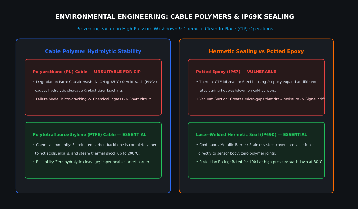
Polyurethane (PU) vs. PTFE Cables in Clean-In-Place (CIP) Operations
Food, dairy, and pharmaceutical plants rely on Clean-In-Place (CIP) sanitation routines:
- Caustic Wash: 1.0% – 3.0% Sodium Hydroxide (NaOH) at 85°C.
- Acid Wash: 0.5% – 2.0% Nitric Acid (HNO₃) at 70°C.
Cable Jacket Comparison
| Cable Polymer | Chemical Resistance | Hydrolytic Stability | Max Temp | CIP Washdown Suitability |
|---|---|---|---|---|
| Polyurethane (PU) | Moderate | Poor (Degrades in hot acid/alkali) | 80°C | Unsuitable (Micro-cracking & short circuits) |
| Polytetrafluoroethylene (PTFE) | Exceptional (Inert to acids/alkalis) | Impermeable | 200°C | Essential (Long-term CIP immunity) |
Laser-Welded Hermetic Sealing (IP69K) vs. Potted Epoxy (IP67)
- Potted Epoxy (IP67): Liquid resin potting suffers from Coefficient of Thermal Expansion (CTE) mismatch during thermal washdown cycles. As the sensor cools, internal vacuum suction pulls moisture into the gauge cavity, lowering insulation resistance.
- Laser-Welded Hermetic Sealing (IP69K): Stainless steel covers are laser-fused directly to the sensor housing, creating a continuous metallic barrier rated for 100 bar high-pressure jet washdown at 80°C.
4. The Electronics Interface: Analog Output vs. Amplified Signals

Signal Attenuation & 6-Wire Sensing Topology
- 4-Wire Topology: Cannot compensate for cable resistance changes caused by distance or temperature fluctuation.
- 6-Wire Topology: Utilizes two dedicated high-impedance Sense Lines to measure actual voltage at the sensor bridge, allowing the weight controller to dynamically adjust excitation output.
Amplified 4–20 mA Current Loops & Shielding Guidelines
In high-EMI environments near Variable Frequency Drives (VFDs) and heavy motors, converting raw millivolts to an amplified 4–20 mA current loop eliminates voltage drop and electromagnetic noise.
Shielding & Conduit Rules:
- Twisted-Pair Shielded Cable: Ensures induced magnetic noise affects both signal lines equally for common-mode rejection.
- Single-Point Chassis Grounding: Connect cable drain wires to Earth ground at the control panel chassis only. Dual-ended grounding creates ground loops.
- Physical Conduit Separation: Maintain at least 12 inches of clearance between signal cables and high-voltage AC lines. Cross power lines at strict 90-degree angles.
5. Interactive Selection & Procurement Framework
B2B Industrial Load Cell Procurement Matrix
| Load Vector Type | Form Factor | Capacity Range | Key Structural Limitation | Primary Industrial Application |
|---|---|---|---|---|
| Pure Tension | S-Beam | 50 lbs – 10,000 lbs | Poor off-axis side-load rejection; sensitive to torque | Suspended hoppers, material tensile testers, crane scales |
| Pure Compression | Canister | 10,000 lbs – 500,000 lbs | High vertical profile; vulnerable to overturning moments | Truck weighbridges, heavy rail scales, outdoor silos |
| Universal Low-Profile | Pancake | 5,000 lbs – 100,000 lbs | Requires high-precision flat mounting (0.0005 in/in) | Component durability testing, dynamic presses, flight simulators |
| Compression Shear | Shear Beam | 1,000 lbs – 20,000 lbs | Capacity ceiling; sensitive to deck plate twisting | Floor scales, process blending tanks, vessel weighing |
6. Industrial Product Integration Analysis
Case Study 1: Heavy-Duty Stainless Steel Canister Cell
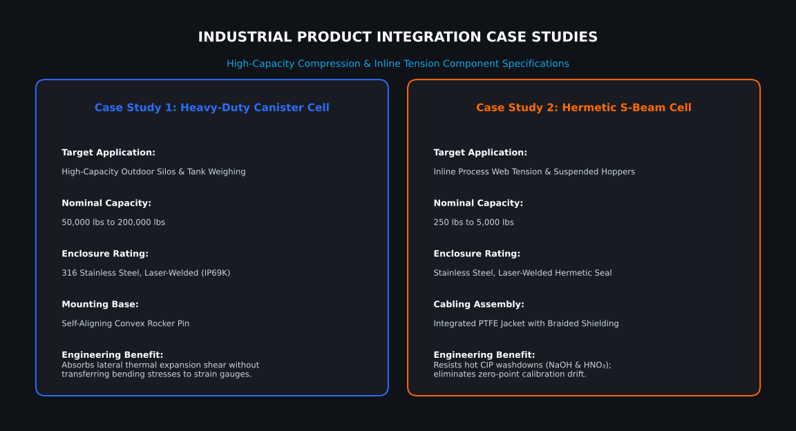
- Target Application: Heavy outdoor storage silos and raw material hoppers.
- Engineering Justification: Built from 316 stainless steel with laser-welded IP69K sealing to withstand weather extremes and chemical washdowns. Integrated convex rocker pin bases allow silo legs to expand thermally without transferring damaging lateral shear into internal strain gauges.
Case Study 2: Hermetically Sealed S-Beam Cell
- Target Application: Suspended batching hoppers and inline material web tension control.
- Engineering Justification: Laser-welded enclosure seals central strain gauge cavity against CIP moisture ingress. Shielded PTFE cable prevents polymer breakdown during daily caustic washdowns.
7. Technical Troubleshooting & FAQ
Why is my weight indicator showing a wandering zero-point calibration?
Zero-point calibration drift indicates moisture ingress inside the strain gauge cavity or junction box. Moisture lowers insulation resistance across the Wheatstone bridge arms, causing erratic signal shifts.
- Diagnostic Step: Disconnect sensor leads and measure insulation resistance between the stainless steel housing and each wire using a digital multimeter. A healthy sensor displays > 5,000 MΩ. Readings below 100 MΩ confirm moisture contamination.
Can I interchange 4-wire and 6-wire load cells?
You can replace a 4-wire cell with a 6-wire cell by jumpering the Sense lines directly to their respective Excitation terminals at the controller. However, replacing a 6-wire cell with a 4-wire cell on cable runs over 30 feet causes measurement drift because the system loses excitation drop compensation.
How do I protect load cells from welding damage and lightning strikes?
Industrial arc welding and lightning introduce high surge currents that vaporize thin strain gauge foil patterns.
- Grounding Bypass Straps: Install heavy copper grounding straps directly across top and bottom mounting plates to bypass the sensor.
- Welding Ground Placement: Always attach the arc welder’s ground clamp directly to the workpiece being welded, never across the load cell assembly.
8. Operational Action Plan: Engineering & Sourcing Roadmap
- Map Force Vectors: Calculate maximum vertical load and estimate lateral forces from wind or thermal expansion. Select Canister for heavy vertical loads, S-Beam for suspended tension, or Pancake for tight vertical clearances.
- Evaluate Environmental Hazards: Specify laser-welded stainless steel (IP69K) and PTFE cabling for washdown or CIP chemical environments.
- Calculate Cable Distance: Use 6-wire sensing topologies for runs exceeding 30 feet, or inline 4–20 mA transmitters near high-EMI VFD equipment.
- Install Structural Protections: Integrate self-aligning rocker mounts and heavy copper grounding straps across all load cell assemblies.