
Digital Load Cell Architecture, Signal Conditioning, and Industrial Bus Integration
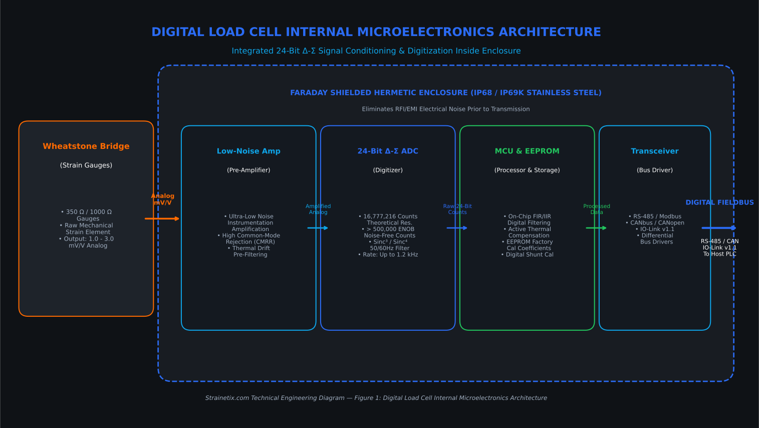
Digital load cells integrate local 24-bit delta-sigma (Δ-Σ) signal conditioning and analog-to-digital conversion directly inside the sensor housing, converting low-level strain gauge Wheatstone bridge signals (1.0–3.0 mV/V) into high-noise-immune digital outputs (RS-485, CANbus, IO-Link). By transmitting digitized data over differential fieldbus lines, digital load cells eliminate signal degradation, remove susceptibility to electromagnetic interference (EMI) from VFDs, enable individual cell addressing, and eliminate physical analog summing junction boxes in multi-sensor scale installations.
NOTE: Digital load cells perform analog-to-digital conversion directly at the internal strain gauge bridge. For a detailed breakdown of underlying Wheatstone bridge math, gauge factor dynamics, and 6-wire sense circuits, see our Foil Strain Gauge Engineering Guide. To compare analog vs. digital sensor flexures and mounting hardware, visit our Industrial Load Cell Selection & Sourcing Guide.
1. Introduction to Digital Load Cells & Internal Architecture
Analog vs. Digital Load Cell Design Fundamentals
Traditional strain gauge Wheatstone bridges output low-level analog signals (typically 1.0 to 3.0 mV/V full scale). In industrial environments with long cable runs (50+ meters), these microvolt-level signals are highly susceptible to voltage drops, electromagnetic interference (EMI) from Variable Frequency Drives (VFDs), and thermal drift along cabling.
A digital load cell integrates precision signal conditioning, amplification, thermal sensing, microprocessor control, and an Analog-to-Digital Converter (ADC) directly within the sensor enclosure. Digitizing the signal at the point of strain measurement isolates the data from external noise sources, providing high signal integrity and enabling long-distance transmission over standard industrial fieldbuses.
Integrated Microelectronics & 24-Bit Δ-Σ Analog-to-Digital Converters (ADC)
Inside the sensor’s hermetically sealed housing, a multi-layer surface-mount PCB houses the core instrumentation chain:
- Low-Noise Instrumentation Amplifier: Pre-amplifies microvolt bridge output.
- 24-Bit Delta-Sigma (Δ-Σ) ADC: Provides high-resolution conversion with built-in digital filtering (sinc³ / sinc⁴) to attenuate 50/60 Hz line noise.
- On-Chip Microcontroller & EEPROM: Executes internal FIR filtering, applies factory calibration polynomials, performs active thermal compensation, and handles bus protocol stacks.
- Differential Transceiver: Drives RS-485, CANbus, or IO-Link physical layers.
Mathematical Resolution & Quantization Equation
The theoretical digital resolution of a 24-bit Δ-Σ ADC is determined by:
Counts = 2²⁴ = 16,777,216 counts
Resolution = Full Scale Capacity / 16,777,216
Under real-world thermal noise and industrial EMI, the Effective Number of Bits (ENOB) is typically between 19 and 21 bits, yielding over 500,000 internal noise-free counts—far exceeding standard 10,000-count legal-for-trade requirements.
2. Digital Signal Processing, Protocols & Industrial Bus Topology
Serial Communication Protocols: RS-485, CANbus, CANopen & IO-Link
Digital load cells communicate over standard open industrial fieldbus protocols including RS-485 (Modbus RTU), CANbus (CANopen / ISO 11898), and IO-Link v1.1. Operating over differential signaling lines, these open protocols eliminate vendor lock-in, support multi-drop daisy-chain topologies of up to 32 nodes per segment, and transmit real-time weight, diagnostics, and cell temperature directly into PLCs (Siemens, Rockwell, Beckhoff).
- RS-485 / Modbus RTU:
- Uses half-duplex differential voltage signaling across twisted shielded pairs (120 Ω line termination).
- Multi-drop topology supports up to 32 addresses per network segment.
- Standard baud rates: 9,600 to 115,200 bps.
- CANbus / CANopen (ISO 11898):
- High-reliability, message-based protocol with non-destructive bitwise arbitration.
- Ideal for mobile machinery, outdoor heavy equipment, and high-vibration applications.
- IO-Link (Point-to-Point v1.1):
- Modern Industry 4.0 standard providing cyclic process weight data alongside acyclic status flags and diagnostic parameters.
- Directly connects to IO-Link masters without complex communication gateways.
Noise Immunity & EMI/RFI Shielding in Industrial Environments
Analog millivolt cables act as high-impedance antennas picking up radio frequency interference (RFI) and transient voltage spikes from nearby VFDs, high-voltage contactors, and induction heaters. Digital load cells convert raw bridge voltages to binary frames inside a metallic Faraday shield. Standard differential transmission cancels common-mode noise across A and B signal lines according to:
V_differential = V_A – V_B
Even if EMI shifts the absolute potential of both lines by several volts, the differential potential remains unperturbed, ensuring zero weight reading jitter near 480V VFD motor drives.
Multi-Cell Array Integration Without Analog Summing Junction Boxes
LEGACY ANALOG SYSTEM (Single Point Failure Mode):

Elimination of Junction Boxes
In traditional multi-cell systems (e.g., 4-cell hopper or truck scale), analog output signals must be manually trimmed and combined using trimming potentiometers inside a physical summing junction box. Junction boxes are the primary point of failure in industrial scale systems due to moisture ingress, potentiometer corrosion, and thermal drift.
Digital load cells connect via a single multi-drop daisy-chain bus. Each load cell possesses a unique network node address. The host PLC or indicator polls each cell individually, calculating total weight algorithmically while performing real-time center-of-gravity (CoG) analysis and corner load imbalance monitoring.
3. Mathematical Formulas, Calibration & Signal Conditioning
Digital Output Scaling & Compensation Equations
1. Raw-to-Engineering Units Conversion
P_meas = (Code_raw – Code_zero) × [ P_cap / (Code_full – Code_zero) ]
Where:
- P_meas = Calculated applied force (kg, lbs, or N)
- Code_raw = Instantaneous 24-bit ADC output count
- Code_zero = Unloaded zero-reference ADC count stored in EEPROM
- Code_full = Calibration full-scale ADC count
- P_cap = Rated capacity of the load cell
2. Active Thermal Drift Compensation
V_compensated = V_raw – [ α × (T_current – T_ref) + β × (T_current – T_ref)² ]
Where:
- α = Linear temperature coefficient of span/zero
- β = Second-order thermal compensation polynomial factor
- T_current = On-board PCB temperature sensor reading (°C)
- T_ref = Factory reference calibration temperature (typically 20°C)
Shunt Calibration & On-Chip EEPROM Calibration Storage
Digital load cells feature integrated precision internal shunt resistors or firmware-simulated load injection across the Wheatstone bridge. By toggling an internal MOSFET switch, a known electrical unbalance is created to verify ADC scaling and signal path integrity automatically without applying physical test weights.
Onboard non-volatile EEPROM stores:
- Factory serial number and production date
- NIST-traceable zero offset and span calibration coefficients
- Multi-point linearity correction tables
- Overload event logging counter and peak historical load values
4. Sample Modbus RTU Register Map
To assist control engineers in configuring PLC communication drivers, the table below illustrates a standard 16-bit Modbus RTU holding register map for a 24-bit digital load cell:
| Modbus Register | Data Description |
|---|---|
| 40001 | Gross Weight Reading (32-bit IEEE 754 Float, Registers 40001-40002) |
| 40003 | Net Weight Reading (32-bit IEEE 754 Float, Registers 40003-40004) |
| 40005 | Sensor Status Flags (16-bit Int: Bit 0=Normal, Bit 1=Overload, Bit 2=Underload, Bit 3=Hardware Fault) |
| 40006 | Internal Cell Temperature (°C, 16-bit Signed Integer, 0.1°C resolution) |
| 40007 | Excitation Voltage Monitor (mV, 16-bit Unsigned Integer) |
| 40008 | Raw ADC Counts High Word (16-bit Unsigned Integer) |
| 40009 | Raw ADC Counts Low Word (16-bit Unsigned Integer) |
5. Environmental Constraints & Physical Hardware Considerations
IP68 / IP69K Sealing & Hermetic Packaging
For hygienic food processing, CIP (Clean-In-Place) chemical washdowns, and aggressive outdoor chemical storage, digital load cell enclosures utilize:
- Materials: 17-4PH stainless steel or 316L stainless steel bar stock.
- Sealing Method: Full 360° laser-welded glass-to-metal feedthrough headers and laser-welded diaphragms.
- Ingress Rating: IP68 (continuous submersion at 1.5m for 100 hours) and IP69K (high-pressure, high-temperature washdown at 100 bar, 80°C).
Parasitic Loading, Side Load Rejection & Mounting Constraints
Side forces, thermal expansion of vessel mounting structures, and angular misalignment introduce severe bending moments that degrade weight measurement accuracy.
- Rocker Pin Assembly: Self-centering rocker pins isolate side forces while allowing horizontal expansion.
- Flexure Stay Rods: Restrain vessel movement horizontally without constraining vertical force vector transmission.
- Mechanical Stress Verification: Strainetix performs Mechanical Stress Verification on mounting hardware to ensure parasitic side loads contribute < 0.02% full-scale error.
6. Industrial Digital Load Cell Specification Classes & Selection Guide
1. High-Precision S-Beam Digital Load Cells (Tension / Compression)
- Technical Specifications: Capacities ranging from 250 lbs to 10,000 lbs (1.1 kN to 44.5 kN); integrated 24-bit Δ-Σ ADC with selectable sampling rates up to 1,200 Hz; RS-485 Modbus RTU / ASCII serial interface; IP67 anodized aerospace aluminum or 17-4PH stainless steel enclosure.
- Engineering Application Rationale: Specified for industrial tension/compression material testing, dynamic checkweighing, and hanging hopper scales where long cable runs to host PLCs typically introduce electrical noise in analog systems.
2. Heavy-Duty CANbus Compression Load Cells (High Capacity)
- Technical Specifications: Capacities ranging from 10 to 100 metric tons; CANopen / ISO 11898 fieldbus interface with hardware arbitration; IP69K hermetically laser-welded 17-4PH stainless steel enclosure; integrated internal temperature sensor.
- Engineering Application Rationale: Engineered for outdoor vehicle scales, bulk storage silos, and mobile heavy equipment requiring high EMI immunity and active real-time thermal drift correction.